ProductsProduct
-
Classification
Three-phase separator Multiport selector valve Manifold Gauge tank Gas booster skids Water bath heater LNG CNG Natural gas dehydration unit Debris catcher Heat exchanger Two-phase separator Multi-cyclone separator Gas sweetening units Pressure vessel Natural gas filter separator Natural gas circulation separator Buffer tank Desander Gas recovery unit
HOTLINE
+86 158 6190 3617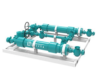
Debris catcher
-
Debris catcher is installed between the high-pressure manifold of the surface process and the gas production wellhead. After the wellbore fluid reverses to the surface, it first enters into the inside of the filter cartridge
- HOTLINE: +86 158 6190 3617
-

-
Details
-
Contact

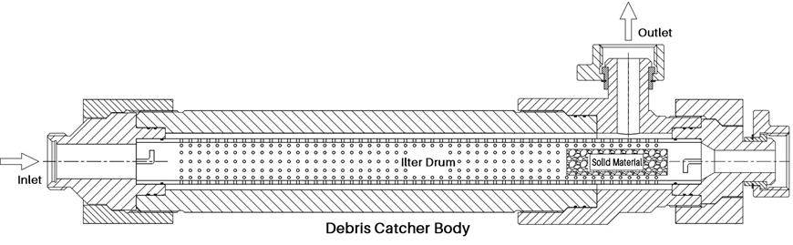
Debris catcher is installed between the high-pressure manifold of the surface process and the gas production wellhead. After the wellbore fluid reverses to the surface, it first enters into the inside of the filter cartridge, and intercepts the debris, cuttings, perforation residue and other solid substances in the fluid through the built-in filter cartridge, and then flows out from the side through the filter hole. The solid substances is blocked inside by the filter cartridge, so as to realize the separation of solid and fluid, as well as to avoid a large number of solid substances into the follow-up process, thus effectively prevent the blockage of the ground process and excessive wear of choke valve, which resulting in shorter service life. The working principle of the debris catcher is shown in Figure 1.

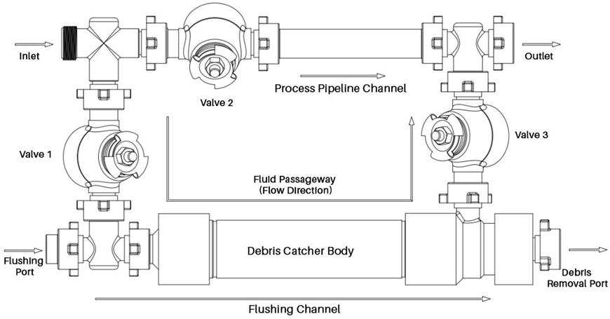
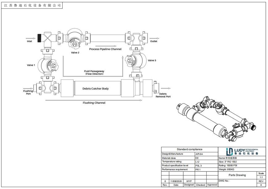
(1) When there is no solid substances in the wellbore during normal test operation, the flow mainly passes through the main pipeline channel; Then the flow direction works as follows: fluid enters from inlet → passes through valve 2 → main pipeline channel → flows out from outlet; valve 1 and valve 3 remain closed.
(2) When it is found that there is solid substances flowing out with the fluid in the wellbore, the process needs to be changed from passing through the main pipe channel to passing through the debris catcher body, and the solid substances is filtered through the filter cartridge in the debris catcher. Then the flow works as follows: fluid enters from inlet → (valve 2 is closed) through valve 1 (there is a normally closed valve at the flushing port, which is opened during flushing) → fluid is filtered through catcher body → through valve 3 (there is a normally closed valve at the discharge port, which is opened during flushing) → outlet flows out; then valve 2 and flushing port and the valves at the discharge port are all closed.
(3) When it is judged that the solid substances in the catcher is nearly full during the operation, the filter cartridge needs to be cleaned and rinsed in time. The process works as follows:
① Close valve 1, 2, and 3.
② Slowly open the valve at the discharge port to relieve pressure. Pay attention to protection and keep away from the outlet during pressure relief. Observe the outlet condition to ensure that the pressure relief is normal and complete.
③ After the pressure relief is completed, open the valve at the flushing port and flush with water pump until the outflow liquid is clear and there is no obvious solid substance.
④ Close the valve at the flushing port and the valve at the discharge port, and the flushing is completed.
⑤ Open valve 1, wait for the fluid to fill the catcher, open valve 3, the catcher enters the working state, allowing circulation to resume.
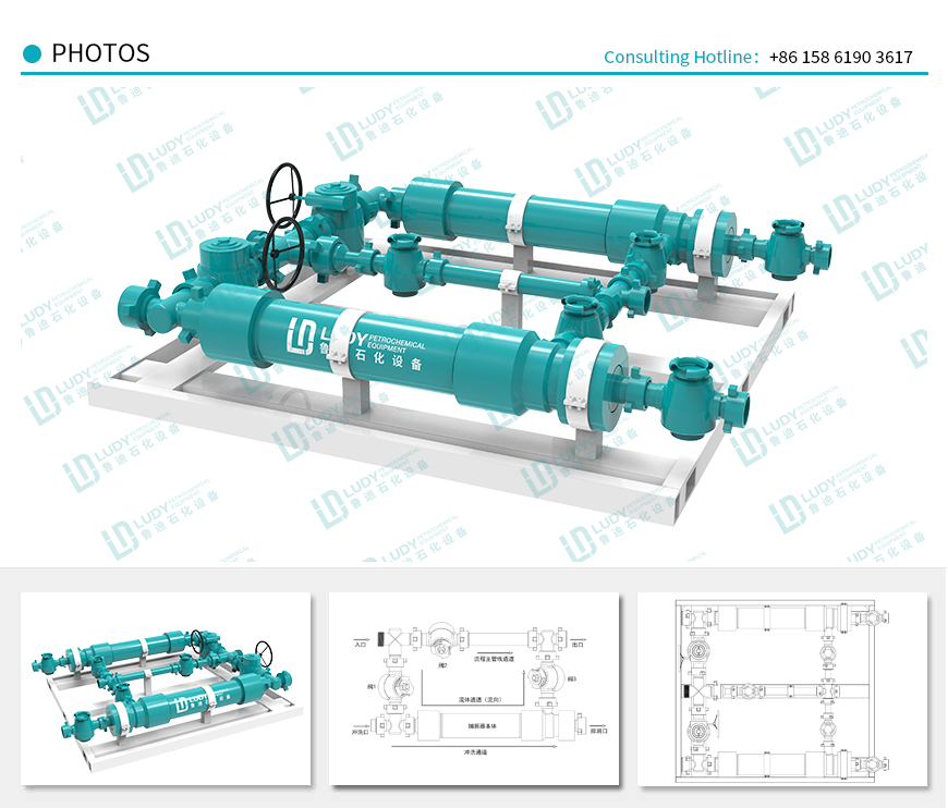
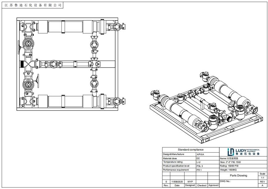
Dual-cylinder Debris Catcher
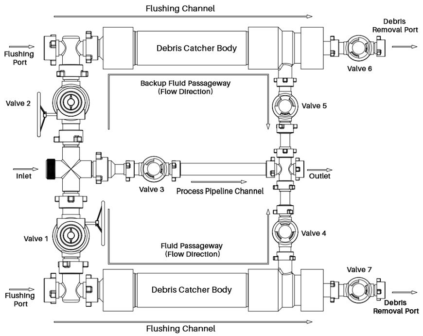
(1) When there is no solid substances in the wellbore during normal test operation, the flow mainly passes through the main pipeline channel; then the flow direction works as follows: fluid enters from inlet → passes through valve 3 → main pipeline channel → flows out from outlet; then valve 1 and 2, valve 4 and 5, valve 6 and 7 remain closed.
(2) When it is found that there is solid substances flowing out with the fluid in the wellbore, the process needs to be changed from passing through the main pipe channel to passing through the catcher body, and the solid substances is filtered through the filter cartridge in the catcher. Then the flow works as follows: fluid enters from inlet → passes through valve 1 (there is a normally closed valve at the flushing port, which is opened during flushing) → fluid is filtered through the catcher body → flows out through valve 4 → outlet; then the valves 2, 5, 6 and 7 as well as the valves connected at the flushing port are closed.
(3) When it is judged that the solid substances in the catcher is nearly full during the operation, the filter cartridge needs to be cleaned and rinsed in time. The process works as follows:
① Close valve 1, valve 4; all valves are now in closed status
② Open valve 2 and 5 to switch the catcher process to the standby route
③ Slowly open valve 7 to relieve pressure. Pay attention to protection and keep away from the outlet during pressure relief. Observe the outlet condition to ensure normal and complete pressure relief.
④ After the pressure relief is completed, open the valve at the flushing port and flush with water pump until the outflow liquid is clear and there is no obvious solid substance.
⑤ Close the valve of the flushing port and valve 7, and the flushing is completed.
When the dual-cylinder debris filter needs to be washed, just switch the process to the standby channel, close the valve after the cleaning of the pipeline to be cleaned, and repeat the above steps when cleaning is needed next time.
Structure quality of debris catcher
The main body of the debris catcher is composed of cylinder, filter pipe, corresponding valve and reducing flange (Figure 1)

Temperature Class: | P to U |
Working Pressure: | 15000 PSI |
Code: | API 6A / ASME VIII Div.2 |
Inlet: | 3”1502 |
Outlet: | 2”1502 |
Filter hole diameter: | 6mm |
Internal volume: | 16L |
Connection form of inlet and outlet:
Single-cylinder debris catcher - union connection with inlet and outlet of 3"FIG 1502
Dual-cylinder debris catcher - union connection with 3"FIG 1502 inlet and 2"FIG 1502 outlet

Single-cylinder debris catcher
Dual-cylinder debris catcher
Leave a message
* is required
- *